
It’s Time for Custom Engineered Solutions
October 26, 2022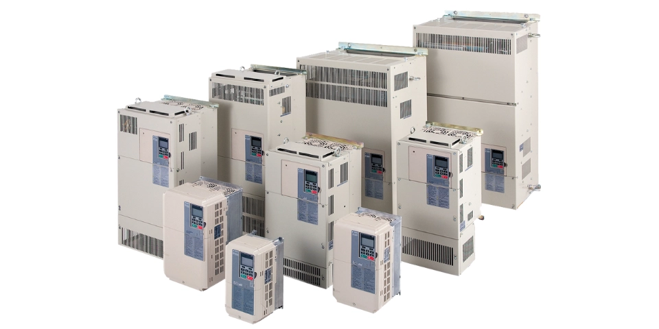
Which VFD Motor Control Method Is Best for You?
February 16, 2023

Variable frequency drives (VFDs) are an integral part of industry technology. VFDs control the speed of AC motors, fans, pumps, etc. and should always be in your arsenal. Although they have become standard technology for many industries, they are not resistant to myths and misunderstandings. These myths can potentially interrupt VFD solutions for original equipment manufacturers (OEMs) wanting to employ them.
To prevent a misstep of believing any myths, here are the most common misconceptions about VFDs that engineers will come across.
1. VFDs Have a Sinusoidal Output
To start an AC induction motor, three-phase leads must be connected to three-phase power. In North America, the average frequency is 60 Hz with a voltage mass(?) of 230 V, 460 V, or 575 V. Sine waves are created from the voltage, resulting in a current waveform that equals the frequency when the motor leads are checked. The output of a VFD is entirely different.
For a VFD to work properly, it is connected to a rectifier consisting of multiple diodes. These diodes allow electricity to flow in one direction while blocking it from returning the same way. VFDs usually work in a three-phase input connected to a fixed DC voltage. This voltage is filtered using DC bus capacitors to smooth out rectified DCs into a constant voltage.
After the ripples are smoothed, the DC flows into insulated-gate bipolar transistor (IGBT) pairs, one for each output phase. The pairs act as switches that open and close, controlling the flow of electricity. Essentially, this process converts DC voltage into AC.
IGBT pairs give users control over how long the switch is turned on or held off, allowing the root mean square (RMS) value of output voltage to be determined. Because the relationship between output voltage and output frequency is fixed and linear, there is an allowance for constant torque. Output frequency and output voltage should increase at the same rate, keeping the motor flux constant.
The waveform resulting from the operation that is applied to the motor winding is not sinusoidal.
2. VFDs Are All Made the Same
Most VFDs have the same basic components:
- Bridge rectifier
- DC bus capacitor bank
- Output inverter section
- Soft charging circuit
While these are mostly the same across the board, there are many ways they can differ:
- How the inverter switches
- Reliability of all components
- Efficiency of thermal dissipation scheme
Some versions of VFDs have a three-level output section. This allows the voltage to pulsate between half-bus, voltage-level pulses, and full-bus pulses. Using a three-level output reduces the voltage amplification at the motor.
Some VFDs use a matrix-style inverter without a DC bus or bridge rectifier altogether. These VFDs can connect to any incoming phase voltages due to the bidirectional switches they use.
3. Power Factor (PF) Problems Can Be Solved with a VFD
VFDs are equipped with internal capacitor buses that dispense the reactive current that certain motors require. These buses can lower the displacement PF, which then protects the AC line from being the source of reactive currents itself.
Before calculating PF, you must include the reactive power needed by the harmonics created when AC voltage is directed to DC. Harmonics, in short, are the currents or voltages with frequencies that multiply the power frequency. For example, the first frequency is 60 Hz, the second is 120 Hz, and so on.
Another important consideration is that the current driven by the diode bridge from the AC line to the DC bus isn’t continuous. Diodes are only on when they are at the peak of each phase of the positive and negative portions of sine waves. This causes ripples in the input current before the DC bus capacitor smooths them out.
To calculate true PF, you must add the displacement PF and the total harmonic distortion (THD) with the following equation:
True PF = Displacement PF1 + THD2
4. Motors Can Run at Any Speed with VFDs
VFDs can change their output voltage and frequency to enable motors to run faster or slower than at regular operating speeds. But there are also a few conditions you must be aware of:
- Cooling: Totally enclosed fan-cooled (TEFC) motors can run at slower speeds, but because less cooling air can get to them, it is not always recommended. We do not suggest operating these motors at a full load below 15 Hz.
- Speed: It is best practice not to exceed the maximum safe operating speed for any motor, regardless of using a VFD or not.
- Power: VFDs can run out of voltage if motors approach their maximum operating speed.
5. The Output Current Should Not Be Higher than the Input Current of a VFD
A VFD’s input current should be slightly higher than its output current. But you will see that the input current is much lower when measured. The primary consideration in measurement should be power, not current.
The power equation is as follows:
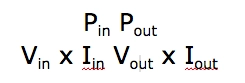
The input voltage is always the AC line voltage; the output voltage varies with the speed based on the volts-per-hertz (V/f) pattern.
Generally, induction motors have two current units:
- Current that produces the magnetic field (rotates the motor)
- Current that produces torque
Currents that produce magnetic fields will not vary with speed normally. During low-torque conditions, the output current may seem higher than the input current. This happens because input current mirrors the current that produces torque (plus Harmonics) but will ignore the current that creates the magnetic field, even at full load conditions.
Remember, you need to balance input and output power, not current.
VFD Solutions for Your Business
Avoiding these myths and misconceptions can save your business time, money, reputation, and more. Make sure you are working with experts in the field who can help you choose which drive and motor products are perfect for you.
Motion Automation Intelligence has the experts you need. Contact us today.